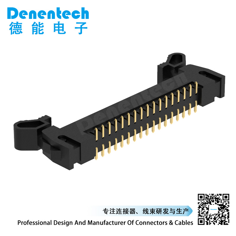
The ejector connector is a European-style connector, which is classified according to the actual use of the connector. It is named because its shape is similar to that of a horn. The ejector connector is an internal wiring device that is very simple to use. According to requirements, the outer dimensions of the ejector connector are commonly used in three specifications: 1.27 pitch, 2.00 pitch, and 2.54 pitch; according to the difference in pitch, the diameter of the square pin used is also changed accordingly. The contact surface between the bottom and the PCB board can be designed as SMT patch type or DIP direct insertion 180 degrees.

The Ejector Header can be made either wire-to-board or board-to-board. The ejector header has an anti-loosening function. It can be in close contact with the wire end or the board end to prevent it from falling off due to collision during use.
The ejector connector usually needs to pay attention to the insertion direction, perpendicular to the insertion direction and inclination when using:
1. Insertion direction: When the connector is fully inserted to U=14.2, the specified contact resistance should be ensured.
2. Perpendicular to the insertion direction: If the printed board or fixed board-mounted connector is mounted floating, the design of the free and fixed board-mounted connector should give an adjustable displacement of at least 1mm.
3. Inclination: The design of free and fixed board-mounted connectors allows for inclination errors, the longitudinal axis is ±4°, and the horizontal axis is ±4°.